
Who might need a slope stability survey? Typically we work with people who are looking to buy, sell or develop property in Cornwall and are concerned about lanslides, landslips and rockfall. It may be a coastal property with sea cliffs, a former quarry or it may simply be a hillside or sloping site. Slope Stability Assessment is essential in assessing the risk that might be posed to a property or development by ground movement associated with soil or rock slope instability.
When undertaking a slope stability survey it is important to understand the topography, geology and history of a site. There is an important distinction firstly between natural slopes and those that have either been excavated by man (such as quarries) or significantly affected by human activity such as farming or mining. There is also an important distinction between soil and rock slopes, in understanding the mechanism for any slope instability and the nature of a collapse, be it landslide (landslip) or rockfall.
Only when these factors are understood and assessed can slope stabilisation be undertaken (if required), through the implementation of appropriate slope stability methods.

The first and arguably most important stage of any slope stability survey is for the engineer to develop a holistic understanding of the landscape in which the slope exists, it is important to understand how the landscape was formed – be it coastal, fluvial, glacial or other? It is important to understand the erosional or depositional processes that may be at play, and the impact these may have on the nature and state of superficial soils and underlying geology of the site.
What historic human influence may have impacted on that environment? This is particularly pertinent in Cornwall where historic metalliferous mining is prevalent through large swathes of the countryside and there exists thousands of small local quarries excavated into hillsides and sea cliffs. Farming and agriculture can also have dramatic and variable effects on slope stability, from dynamic loading of a slope face associated with plant and vehicles, to the effect of ploughing and the cultivation of fields on surface water drainage and run-off.
There are common risk factors that are influential in almost any scenario where there is a heightened risk of landslide, landslip or rockfall, these may be summarised as follows:
There is an important distinction to be made between soil and rock slopes when defining the ‘types’ of slope failure.
Soil slopes are typically composed of the superficial soils and deposits that exist stratigraphically above rockhead level (bedrock). These may in turn be subdivided into depositional soils – soils that have been emplaced by depositional processes such as fluvial or colluvial activity, and soils that are derived as a result of in-situ weathering of the underlying bedrock. These are soils in an engineering sense (as they are typically well less than 1 Mpa in compressive strength), but they may still retain the residual macro structural features (such as bedding structure) of the underlying bedrock, and are likely to increase in strength with depth as the weathering profile recedes back to unweathered bedrock.
Soil slopes tend to be at a shallower gradient as these soils have achieved a sustainable angle of repose over time, the failure of these slopes then invariably occurs as a result of the disturbance of this soil profile, typically as a result of loading, excavation or saturation, so as to overcome the interparticle cohesion (shear strength) of the soil. The nature of the slope failure is likely to depend both on the depth to rockhead and the presence of groundwater, with rotational type failure more prevalent in deeper soils (depth to rockhead) and slumping or translational type failure more likely in shallower and water-saturated soils.
Rock slopes by comparison are formed from exposed bedrock, either at natural outcrop or exposure, as would be the case in a coastal environment, or exposed through excavation, such as in a quarry setting. The rock slopes tend to be steeper, and may be vertical or sub vertical, with slope failure typically occurring as rockfall. The nature of the slope failure is defined by the quality (strength) of the rock mass and the way in which the discontinuities (joints and fractures) within the rock mass interact with each other and with the slope face. This gives rise to kinematic mechanisms of slope failure such as wedge, toppling or sliding-type failure.

The first stage in the assessment of stability of a soil slope, is to assess and inspect the site to derive as much site-specific information as possible. A comprehensive desk study is required to fully understand the site, this may involve looking at the recorded geology of the site, the hydrology (surface water) and hydrogeology of the site, it is always a good idea to look at historic Ordnance Survey datasets, and other historic datasets that might be available such as satellite imagery or LiDar. The objective of this desk study assessment is to assess the geomorphological characteristics of the site, and how that site may have changed over time.
A walkover inspection of the site may then be carried out. The objective of the walkover assessment is to assess the site for risk factors that may be associated with slope instability, either historic, ongoing or imminent. The first and most obvious of these is the topography, gradient and orientation of the slope, this is followed by an assessment of the make-up of the slope, the nature of the superficial soils and the presence (if any) of shallow bedrock at outcrop or subcrop.
In a simplistic sense we can assess whether the slope is overly steep for the ground conditions; dense granular soils are likely to have a greater in-situ resistance to shear movement than loose sandy or cohesive (clayey) soils. Furthermore, a slope failure circle is unlikely to penetrate into the underlying structured bedrock, so the presence of shallow rockhead effectively limits the volume of slope face material that might be subject to collapse.
Following on we can assess the site for any evidence of slope instability or evidence of ground movement that may be a result of slope instability. The most obvious of these is rockfall, landslide or landslip debris at the base of the slope. Other indicators might include visual indicators that the ground is under tensile stress, these may include the visual observation of tension cracking to the ground surface, subsidence or settlement, or the observation of structural damage to rigid structures such as road surfaces, walls and buildings.
Following this there are a number of risk factors that may be visually assessed, this might include the presence of dynamic or static loading to the slope face, and in particular the upper part of the slope face. This may take the form of vehicle loading as a result of a tractor traversing an agricultural field, or structural loading imposed by a new development. A significant risk factor is the presence of ground or surface water within the slope face, this may take the form of springs or water flow, as indicated by areas of vegetation change to the ground surface, or localised areas of ground saturation. Finally, animal activity such as burrowing and /or excavation of the soil profile is another risk factor to be aware of.
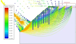
In the event that a site is to be developed and a structural or static load is to be applied to a slope, then further assessment of the slope stability may required using limit equilibrium methods. Limit equilibrium methods investigate the equilibrium of a soil mass on a slope and under the influence of gravity. The method assumes a translational or rotational failure of the slope face on an assumed or known slip surface.
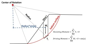
In practice the most commonly used methodology, which forms the basis of most commercial slope stability software is the Bishop’s Method of Slices. This limit equilibrium method separates the slip circle (slope failure) into vertical slices, the mechanical equilibrium of each of the slices is calculated around a defined or derived centre of rotation.
The moment caused by the internal driving forces is then compared against the moment caused by the forces resisting slope failure, to give a nominal Factor of Safety (FoS) which is derived from the ratio of these respective moments.
If the FoS is less than 1.0, the slope may be considered unstable. Refer to Figure i and ii for details.
The first stage of the slope stability assessment of a rock slope is fundamentally the same and will involve a similar desk study as with that of a soil slope. In the event that the site is coastal and the slope in question is a sea cliff or part of a coastline, then additional consideration might be made to the relevant Shoreline Management Plan, which should be available from the local authority, and will detail the management plan for that section of coastline over a short, intermediate and long term.
The assessment of historic Ordnance Survey datasets and aerial imagery is also often very useful in assessing the rate and extent of shoreline erosion and regression of the available time period.
The walkover inspection may then be carried out, though it is important that these works should be undertaken with due regard to the risks inherent in working close to a rock slope. Typically rock slopes are higher and steeper than soils slopes, and by their nature there is an inherent risk of rockfall and collapse. Any such inspection works should be undertaken by experienced personnel, wearing appropriate PPE and with due regard to an acceptable risk assessment and method statement.
The walkover of a rock slope follows the same fundamental methodology as with soil slope, in that we need to gain an understanding of the topography, gradient and orientation of the slope, and look for any evidence of slope instability or evidence of ground movement that may be as a result of slope instability. The most obvious of these is rockfall, landslide or landslip debris at the base of the slope.
However it is also important to assess the state of the rock mass, and to derive a Rock Mass Rating (RMR) in accordance with the methodology presented by Bieniawski (1989), where the rock mass is assessed in terms of the point load strength, Rock Quality Designation (RQD – where available), joint spacing and condition and groundwater conditions. The rock mass is then assigned a rating class from I – V.
The nature and state of the joints and discontinuities within the rock mass will then need to be logged and recorded, relative to the orientation of the slope face. A simple kinematic assessment of the discontinuities within the rock mass may then be used to assess the risk of rockfall from the slope face, and also the principal mechanism whereby that slope failure may occur, be it sliding, wedge or toppling type failure.
In the event that a stability assessment of a rock slope has highlighted an unacceptable risk of rockfall and slope failure, and there is a recommendation for slope stabilisation works, rock slope stability analysis using stereographic projection and kinematic analysis might be required to aid in the design process for slope stabilisation methods.
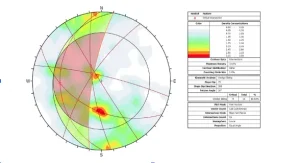
The first stage of the process is to undertake a comprehensive scanline survey of the rock mass, with the objective of methodically logging the discontinuities (faults and fractures) within the rock mass, including their nature, extent and orientation. This scanline information can then be input onto a stereonet, which can project both the discontinuities within the rock mass and the slope face into 3-Dimensions.
Once the stereonet projection is complete, further design parameters are input, including the geology of the slope, and the derived angle of internal friction acting along the discontinuity surfaces. This information can be derived either from expert observation or from geotechnical laboratory testing if required. Once all of the discontinuity data and the design parameters have been input into the model, the kinematic analysis can begin.

The kinematic analysis is a means of modelling the possible modes of failure that may occur in a rock mass, these are typically wedge, sliding or toppling type failure. The kinematic modelling incorporates a statistical analysis which can be used to determine a likelihood of rockfall or slope failure and can then also be used to assess the most likely mechanism for rockfall to occur from the slope face.
This information may then be used to derive an appropriate design solution for slope stabilisation and slope stability methods.
In the event that the slope stability assessment does highlight an unacceptable risk of slope instability, with the potential for future or imminent rockfall, landslide or landslip, then it is likely that there will be a recommendation for further works to be carried out to undertake slope stabilisation using site specific and industry approved slope stabilisation methods.
The most simplistic form of slope stabilisation is simply to reduce the risk factors acting on the slope face, this may include the following:
However in some cases, a more dynamic form of slope stabilisation may be required, which will support and strengthen the slope face and reduce the risk of rockfall, landslide or landslip. These slope stability methods may take the form of reinforcement of the soil or rock slope face, often through the installation of galvanised steel anchors, rock bolts or soil nails, fitted with steel face plates and often used to secure galvanised steel mesh to the slope face. For low strength rock slopes (where the rock mass rating is poor or very poor), the rock bolts and steel mesh may also be used in conjunction with fibre reinforced cement grout which may be sprayed directly onto the slope face (shotcrete), or masonry installed directly onto the slope face.
For development sites on sloping ground, it may simply be sufficient to incorporate appropriate retaining structures into the development plan. However the retaining structures must be of appropriate strength and rigidity to retain the soils on the hillside, and it is imperative that appropriate drainage is incorporated into the design to prevent the accumulation of groundwater behind the structure.
Take a look at our LinkedIn page for more details and useful content: https://www.linkedin.com/company/slope-stability-south-west/?viewAsMember=true